home
back
EuroPi for AE modular
inspired by this forum post and the open-source EuroPi design by Allen Synthesis
the main goals:
- hardware adjustments to meet the AE 0-5v standard
- any additional software adjustments to meet the same
- squeeze everything into an AE format 2U module (100x50mm, 25mm depth)
first prototype
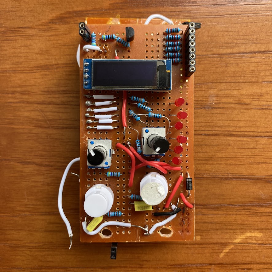
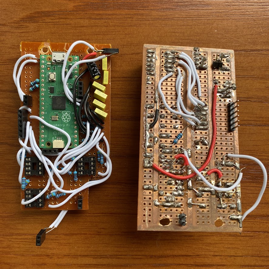
hand-soldered, manually wired on two layers of stripboard to form a sandwich
working:
- screen
- op-amps
- outputs in 0-5v range
- buttons
not working:
- knobs
- outputs are in the wrong order
- digital input not reliable
- analogue input permanently offset
second prototype
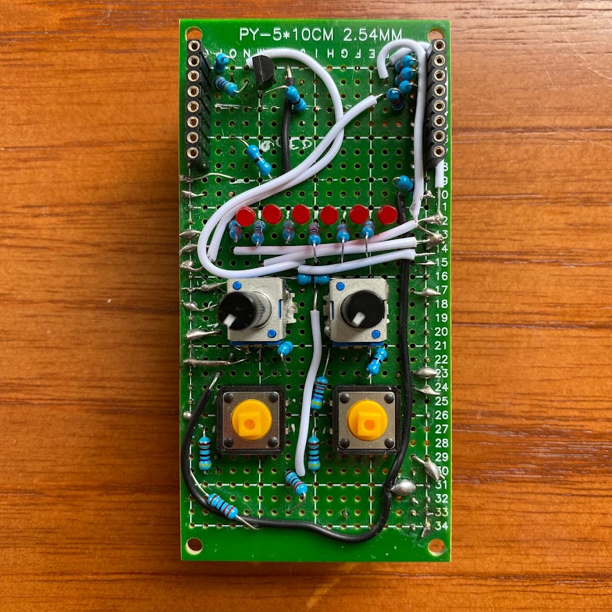
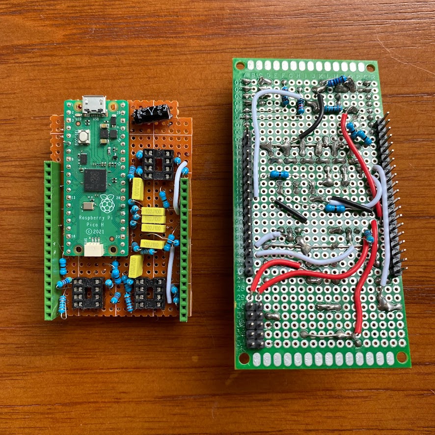
better-quality board, correct dimensions, slightly more sensible wiring layout. accidentally killed the pico while trying to make some changes... it was going well until then.
still causing problems:
- leds
- analogue input slight offset
third prototype
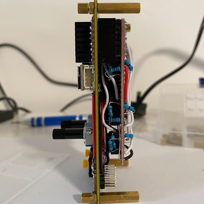
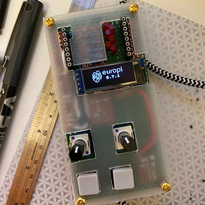
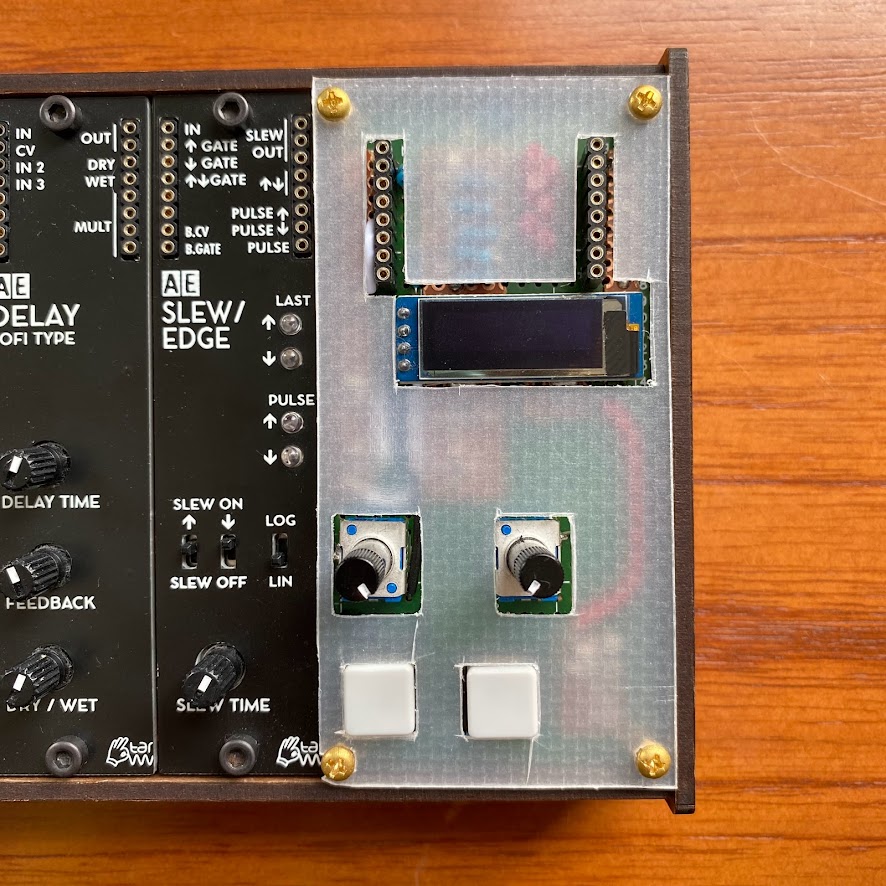
optimised the layout again, this one earned a makeshift front panel
everything was working pretty well here, so time to proceed to easyEDA! because of all the wiring underneath this has to sit a little higher in the case than standard TW modules, but i figure a printed PCB will resolve this
problems:
- leds were still weird, so i ended up just scrapping them entirely
first pcb build


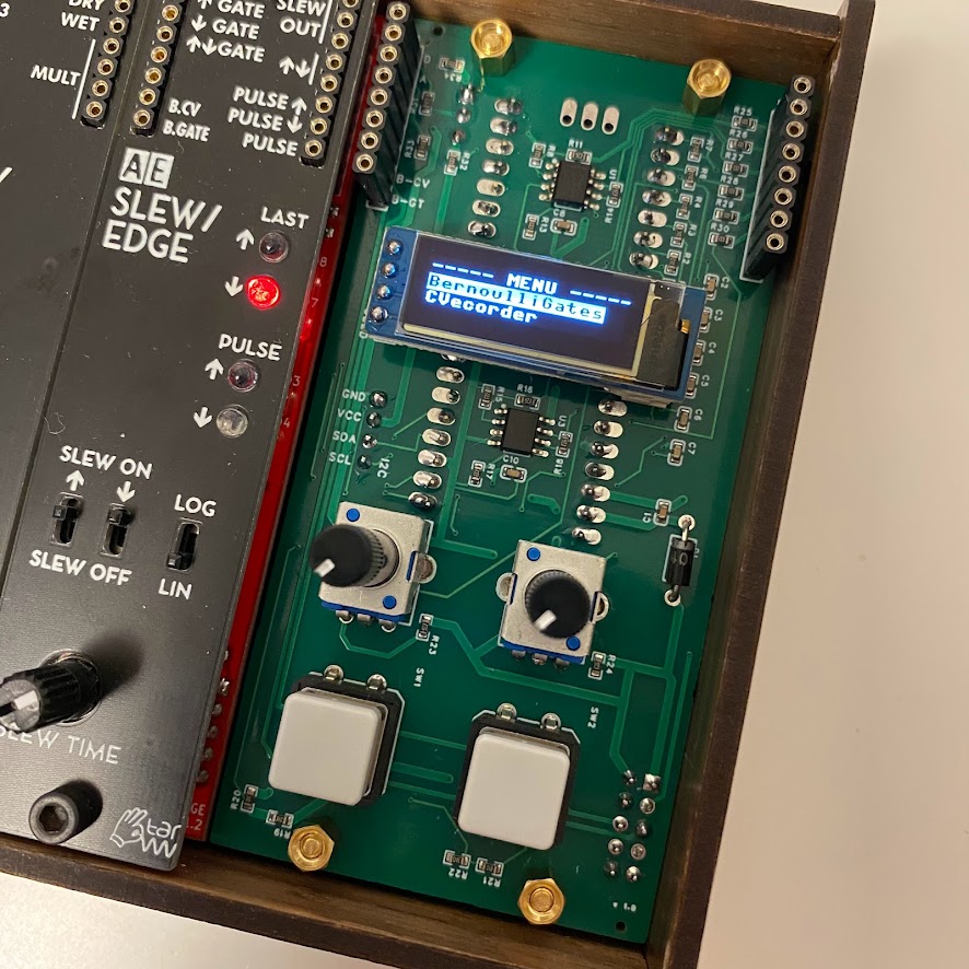
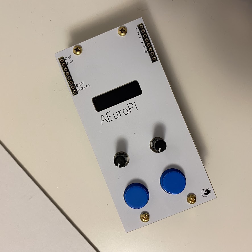
first time pcb making... SMT op-amps saves quite a lot of space. all functions working as expected (after calibration)
want to build your own? gerber files, bom, and pick & place files available here.
putting it all together: build guide
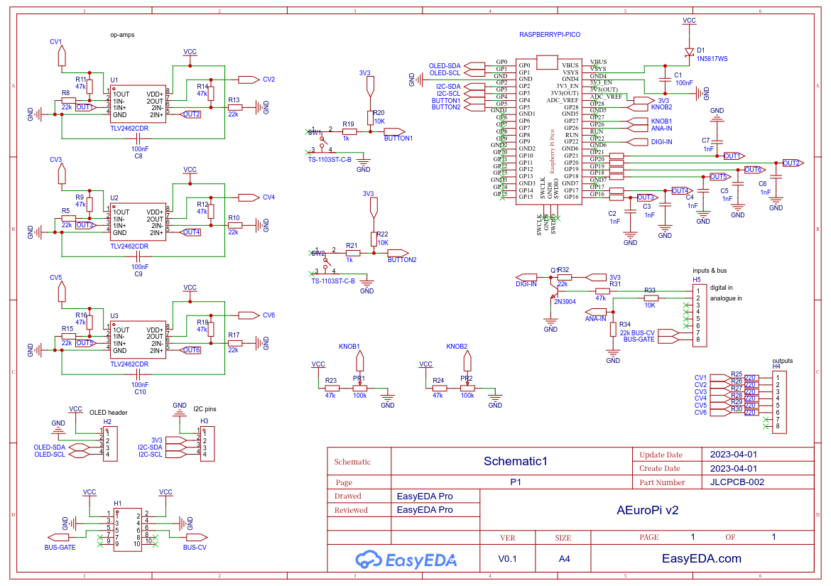
notes:
- removed leds from design entirely
- added an i2c connector on the rear for future expansion (so far untested)
- included midi-cv and gate signals from the bus cable
- added diode on power line to pico to prevent reverse-powering
- (op-amps take power from a separate line so they aren't impacted by voltage drop)
- cap from +5v to gnd before the pico, to smooth out power fluctuations
- changed to round buttons (slightly taller)
- changed to different song huei pots (slightly shorter)
- software: adjusted max voltage value
- software: tweaked pot deadzone
- software: adjusted calibration script for 5v range
- software: customised boot image
having built a few of these now, i can spot a few small amends for future revisions:
- some of the traces run a little close to the board holes, it doesn't seem to be a problem, but might tidy up in future
- i think the 2x5 power pins could stand to be a 1-2mm higher to give the bus cable more wiggle room around the standoffs
- should make the frontpanel holes for the buttons 1mm wider in diameter, so the fit has a bit more tolerance
- frontpanel width is a strict 50mm which leaves a slight gap between modules, should be based on a multiplication of 25.4mm for better fit
- i think the bottom standoff holes should be a fraction lower to align better with the case holes?
- would be nice to have some way of keeping the OLED aligned during soldering
- the i2c pins should probably be 2x4 rather than 1x4
- also not sure if GND > VCC > SDA > SCL is the best order for an i2c connection. there seems to be a bunch of standards
- some of the silkscreen text is a bit small. rory and zeno deserve bigger shoutouts :)


