in ten(ish) easy(ish) steps!
things you'll need: just the soldering basics (iron, solder, solder wick, ideally some kind of 'helping hand' device, wire snippers, masking-type tape). a breadboard is super useful for the first step, if you have one.
note: throughout this build we'll refer to the 'front' and 'back' of the pcb; for this purpose 'front' is the side with the pre-soldered components.
note 2: your board may look slightly different to some of these pictures, as some were taken with an older iteration of the module.

first, take the two 20-pin headers and place them through the pico so that the longest end is pointing out of the 'top' - that is, the side with the USB and reset button on. if you have a breadboard to hand, this is a great way to keep everything straight while soldering.
solder the headers in place from the top. then carefully trim the excess - be warned, these little bits of metal will fly off with some force! consider eye protection! you don't have to worry about trimming them super-short, we're using low-profile sockets for the pico*, so there should be plenty of headroom in the AE case.
*maybe. turns out low-profile headers are kind of hard to come by so some batches may include standard height headers. these still work - i've built several modules with them - but there's very little tolerance in the Tangible Waves case so make sure they're soldered nice and tight on the PCB.


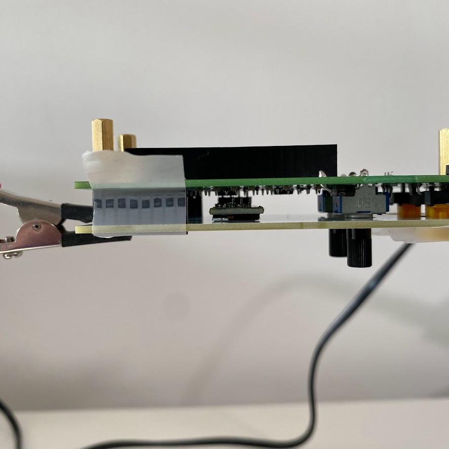
insert the pico into the headers, place the headers on the back of the pcb, and solder in place from the front.
use a piece of tape to make sure the headers stay in place when the board is inverted for soldering. start by soldering the four corners, then fill in the rest.
once done, remove the pico from the headers for the time being.


next, splay the legs of the transistor slightly and feed it through the board from the back. ensure the orientation matches the image on the pcb: the curved side should be facing away from the pico.
solder from the front, then trim the excess with wire clippers.


next insert the diode, this time through the front of the module, and we will solder it from the back. take careful note of the orientation again, which must match the image on the board.
place the 2x5 pin header in position on the back of the board, with the shorter side passing through the pcb and being soldered from the front. you'll probably need to hold this in place with tape again.

take one of the 1x4 pin headers and place it through the holes marked "i2c".
like the 2x5 header, place the shorter pins through the board from the back, and solder from the front. more tape.


place the two potentiometers in position. these will probably hold quite firmly on their own even when the board is turned over. just make sure they're fully inserted and straight. solder all the connections including the large mounting pins which keep them nice and stable.
next, add the two switches and solder in place. make sure they sit nice and level on the pcb while soldering otherwise the frontpanel might press against the buttons once they're in place.


place one capacitor through the panel, facing down. this capacitor can stand vertically. ensure the polarity is correct - the grey strip on the cap should align with the filled-in mark on the pcb. once soldered, turn the board over. the other capacitor goes on the opposite side, but there is less headroom here, so bend the pins so it lies horizonally. take care to ensure the polarity is correct! then solder in place and trim as necessary.
next, attach the four sets of spacers to the board.


time to prepare your OLED, which will likely come with a plastic connection socket attached to one end. we won't be using this, and we don't have a lot of vertical space available, so let's remove it.
snip the 4 little wired connections from the socket to the board. once they're cut you should be able to wriggle the socket off, or just pull it off with some pliers.
take the other 1x4 pins and attach to the OLED, with the longer end pointing 'down'. use tape and try and keep the pins straight so the screen will end up nicely aligned.
solder the pins in place from the top. we're working quite close to the screen here, so take your time.

peel off the OLED protective layer. put the OLED loosely in place, and put your choice of button caps on.


place the six LEDs through the PCB. check the alignment of each - the longer leg should be closest to where the Pico will sit, and the shorter leg will be closer to the edge of the board (see pictures)

screw the frontpanel on, turn the module over, and wiggle each LED into the hole on the front panel before soldering them. note that they won't pass through the hole but will just sit lightly in it (this was sort of a design mistake but it kind of works!)
almost done, but this bit gets a little tricky. with the module turned over, the OLED should have dropped forwards to rest against the frontpanel. make sure it's lying flat, and looks to be straight - you'll have to use your judgement for this. carefully solder it in place, trying not to disturb the positioning by pushing the pins with the iron.
finally, take the AE-style 1x8 pin sockets and place them through the front panel into their position on the pcb. use tape across these to keep them in place, then turn the module over again and solder them in.


your AEuroPi is now ready to receive the pi pico!
don't forget that the pico is mounted 'upside down', ie. with the usb port pointing towards the bottom of the module. the print on the pcb also demonstrates this orientation.
to install the europi firmware, or update to a newer version, there are two options, which depends on whether or not you intend to develop your own scripts.
you will need to use Thonny to install the software onto the raspberry pi, this is not too difficult though. you can follow the original programming instructions for the initial setup: allen synthesis github link
install the ssd1306 library, micropython-europi, and micropython-europi-contrib. follow the instructions to save a copy of contrib/menu.py, naming it main.py and saving it to the root directory. this will set up the main menu to run when the module is powered up.
if you forget to create the main.py nothing will happen when the module is powered up. i have made this mistake several times and panicked on each occasion!
because the original module is designed for eurorack levels, i've adjusted a few of the firmware files and contrib scripts to match the AE standard 0-5v signal range. to date, the only files requiring amendments are:
the amended files are available on my github: https://github.com/fauxcyrillic
download these files, open each of them in Thonny, then choose 'save as', select 'save to raspberry pi pico' and save each of them in the location where the original file is placed, with the same filename, therefore overwriting it.
great! this is super easy! download the latest firmware here: aeuropi firmware v1.14
while holding down the small button on the pico, connect it to your computer. it will appear in your finder/file browser as a removable drive named RP2.
now, drag the .uf2 file you just downloaded onto this drive and it will install and automatically eject. that's it! you can now install your module!
the custom .uf2 includes default calibration values copied from my own built & tested module, so it should be good to go as-is, however if you need to calibrate you should follow these instructions.
i highly recommend the high accuracy calibration, for which you'll require a multimeter and variable source of voltage. if your AE system is based on one of the starter racks, you'll likely have the 2ATT/CV module installed, which is perfect for providing your voltages. switch it to '+5v' mode.