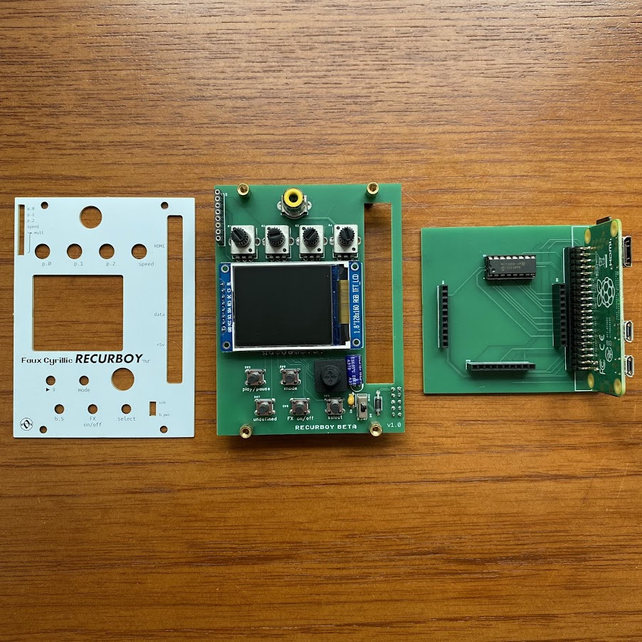
bill of materials:
start with the smaller PCB. solder the two-row GPIO header in place, and a small (1x2) female header next to it. If you have an IC socket, solder it to the board - make sure you're soldering it on the correct side (indicated by the silkscreen), and make sure the orientation is correct. the semicircle cutout on the socket should match the same cutout on the silkscreen.
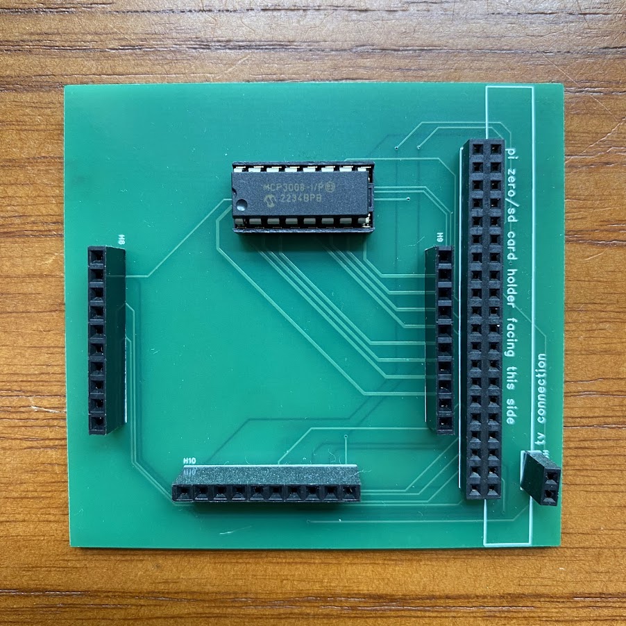
if you're soldering the chip directly to the board, double and triple-check the orientation, as it'll be a lot harder to fix!
on the larger PCB, start by placing the resistors and 1N4148 signal diodes in the centre of the board, these will be underneath the display once completed.

make sure the orientation of the diodes matches the silkscreen! the resistors can be in any orientation.
next, add the bus connector. take care to solder it to the correct side, it should point downwards (sounds silly, but it's easy to get mixed up!)
solder the big 1N4001 diode next to the bus socket. again, watch out for the orientation - this one should point downwards, the opposite of the signal diodes.
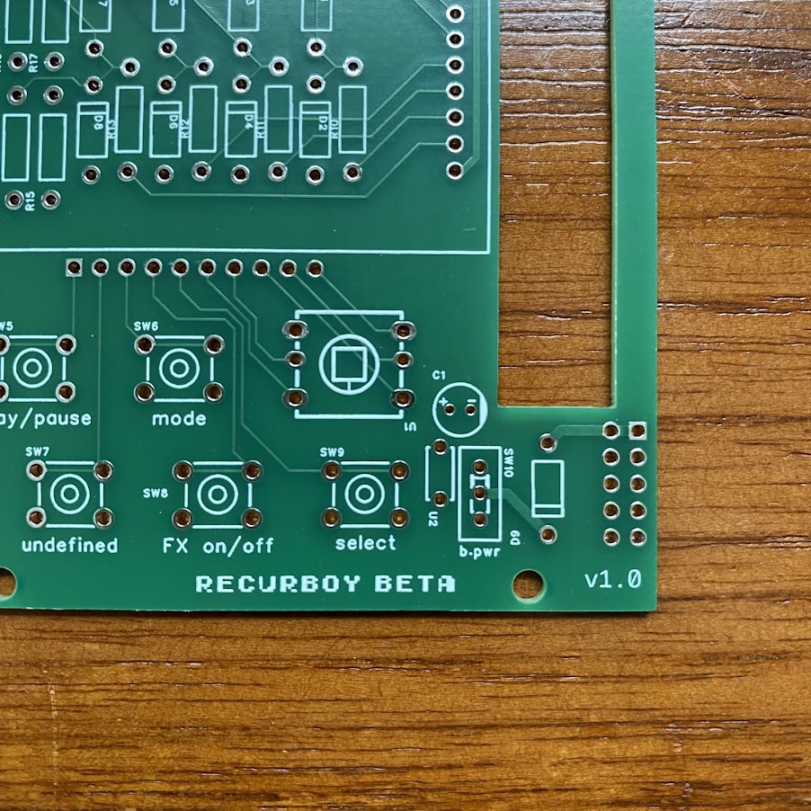
left of this diode, there is a space for a small slide switch. this was intended to choose between powering the Pi from the AE bus, or directly from USB into the Pi Zero. In the end, i don't really recommend using the AE bus (it draws a lot of power), but it's an option. you can either install the switch or you can bridge the top two solder points so it's permanently set to USB power.
(for USB power, connect to the micro USB socket on the Pi as indicated on the frontpanel)
immediately left of this there is a space (U2) for the 100nf ceramic capacitor. above that (C1) is space for the 100uF aluminium capacitor. this is a little tall, so bend it over such that it lies flat on the PCB before soldering. note that unlike the ceramic capacitor, the orientation of this cap *is* important - the line on the side of the component must match the mark on the silkscreen.
next, solder the five-way switch in place.
now would be a good time to install the headers which are used to sandwich the two PCBs together. to make sure these end up mating correctly, it's good to do them in situ. insert the pin headers into the sockets, place each three of them into the appropriate place on the small lower PCB, then put the larger PCB on top so all the pins are through the holes on both sides. put some masking tape or elastic bands around it to hold the thing together while you solder one side, then turn it over also solder the other. once it's all soldered, you can separate the boards again.
i put the socket half of the header on the small PCB facing up, and the pin half on the larger PCB facing down, but it doesn't really matter which way round you do it.


next we'll do the rest of the controls, to make sure these line up nicely with the frontpanel we'll solder them with the panel in place. start by adding the standoffs to the big PCB.
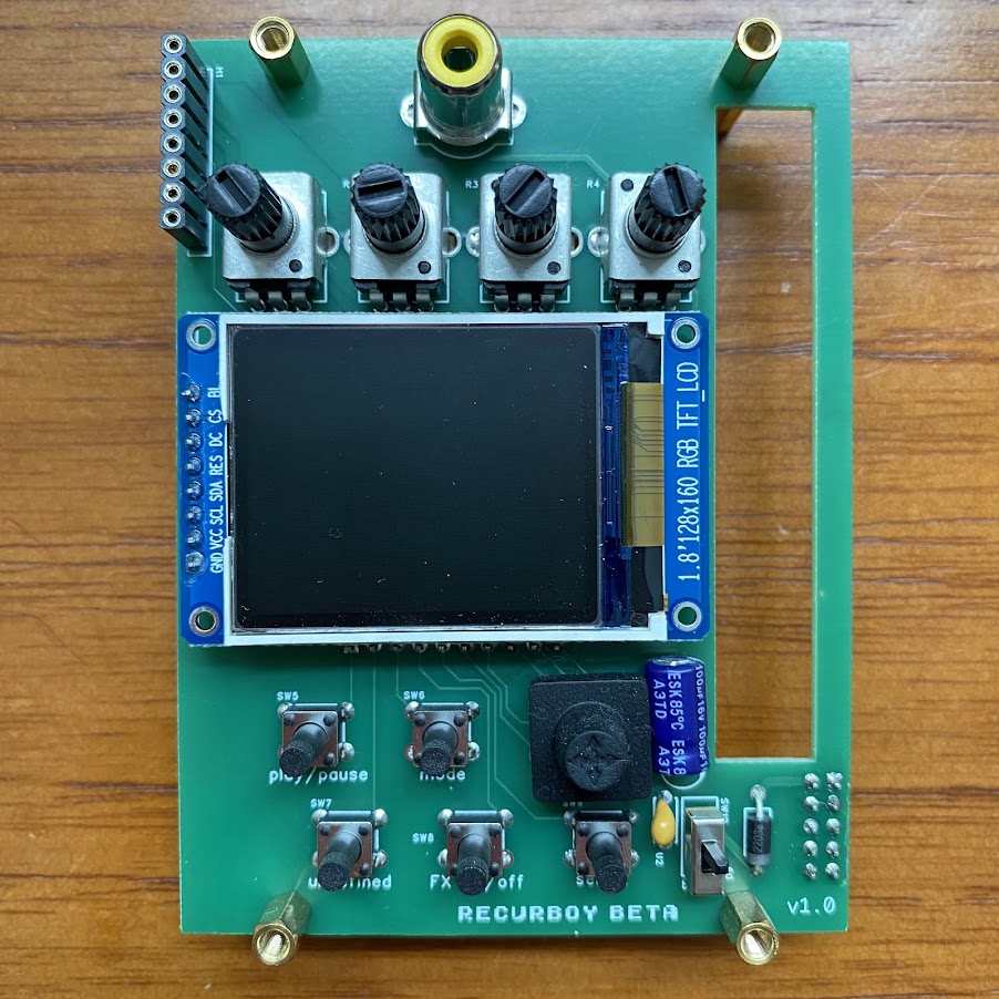
put the five small push buttons, four potentiometers, and the RCA jack in place, then attach the frontpanel, making sure each component lines up with its respective hole. lightly screw the panel in place, then you can turn it over and solder all of those components (they should fit snug enough to stay in place when you turn it over)
once they're done, drop the Tangible Waves pin socket through the panel, wiggle it so it's sitting correctly in the PCB, then put a piece of tape across it so it doesn't drop out again, turn over and solder in place.
now everything else on the front is done, the only thing remaining is to take off the frontpanel again and place the TFT screen in place. re-attach the panel and invert so that the screen is lying flat against the underside of the frontpanel (this may take a bit of prodding and poking to get it level and straight). then solder each of the pins. nearly there!
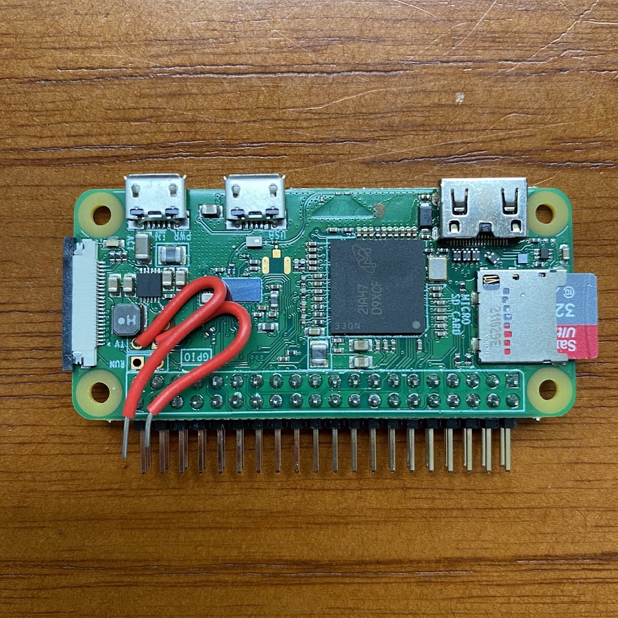
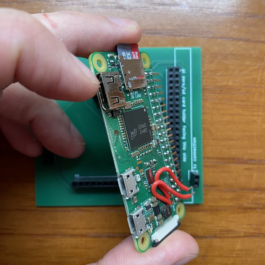
last but certainly not least, solder the right angle connector to your Raspberry Pi Zero. Check the image below and make sure you attach it to the correct side, otherwise your Pi will probably not align with the panel slots!
ignore the implication of the silkscreen on the Pi and solder it so that the main body of the connector is not on the side of the Pi0 with all the chips and the USB sockets etc.
doing this will mean that when inserted into the module correctly (with the SD card facing the top of the module) the Pi will sit slightly to the right of the socket which hosts it, and will line up nicely with the panel slots.
one final thing, solder two short bits of wire to the connections on the Pi labelled 'TV'. the other ends of these wires can then be located in the small two-way socket once the Pi is attached.
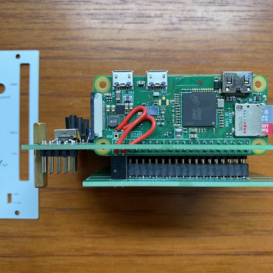
all that remains is to flash your SD card with the recurboy image, install the Pi onto the small PCB, carefully sandwich together the two PCBs, and power up!