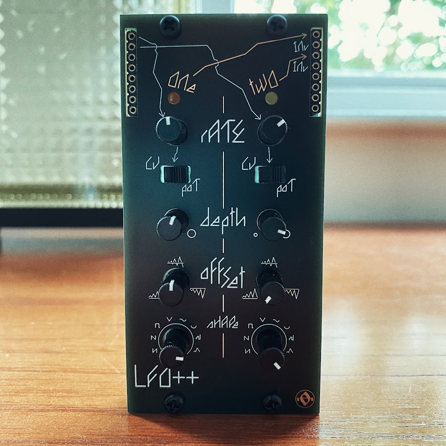
a dual LFO generator with advanced features:
two independent LFOs, each with a main output and inverted output
high-resolution PDM output
selectable manual / CV rate control
depth control - adjusts the overall output level
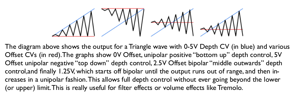
offset - raise or lower the LFO signal within the 0-5v range
eight different wave shapes:interesting LFO cycles can be generated by cross-patching the output of each LFO to the rate input of the other
frequency range: 0.05hz - 25hz (approx 20 seconds - 40ms range)
LFO++ is possible thanks to the excellent work of Electric Druid and their STOMPLFO chip. check out their other stuff!
when a channels slide switch is set to 'cv', the rate control functions as an attenuator. turn fully CW to get the full CV signal.
the depth and offset controls work together [if depth is fully CW then offset has no effect]. with offset CCW the wave operates in a unipolar 'bottom up' style. turning the offset fully CW essentially inverts the signal into a 'top down' wave shape (note that inverted outputs are also provided for each channel). in between minimum and maximum the LFO wave swings around a virtual centre point. at 12-o-clock this will be an even bipolar swing, but the most interesting effects are found with offset between minimum/maximum and the midpoint. here the wave will swing bipolar until it runs out of range in either direction, then increase in a unipolar fashion. (see diagram & explanation from the datasheet below)
the various waveshapes are all fairly self-explanatory - the smooth random function moves between randomly generated points at a linear rate, so movements between voltages which are far apart will occur quickly, while movement between similar voltages will be slower.
experiment with cross-modulation: set channel one to pot control and one of the random waveshapes, then set channel two to CV rate input (remember to turn the rate attenuator up!) and patch the output of channel one into it. set channel two to a looping wave like a sine or sawtooth and see that you get some chaotic rate changes from the cross-modulation. now patch channel two output to a filter or VCA or somesuch!